How Dimmers Work
What is a Dimmer?
A modern dimmer is an electronic device designed to regulate light output of incandescent and halogen lamps; and fluorescent lamps in fixtures equipped with special dimming ballasts. They can also dim some modern LED lamps,
How does a lamp dimmer work
A light dimmer works by essentially chopping parts out of the AC voltage. This allows only parts of the waveform to pass to the lamp. The brightness of the lamp is determined by the power transferred to it, so the more the waveform is chopped, the more it dims.
Mains power is comprised of an alternating current that flows in one direction and then in the other, along the cable, at the rate of 50 or 60 cycles per second (known as Hertz). The value 50 or 60Hz is dependent on the countries power system. The current alternates back and forth changing direction at the zero point. If we were to look at this waveform it would appear as a stretched S shape on its side ~. Draw a line through the middle and this is what is called the zero crossing point. At this instant in time no current is flowing in either direction. This is the point at which a dimmer is electronically synchronized to turn the power ON or OFF. By chopping the waveform at the zero-crossing point, smooth dimming can be achieved without the lamp flickering. This turning on and off of the power device occurs every time the mains crossing point is reached (half phase), 100 or 120 times per second.
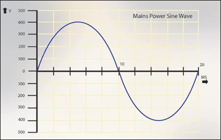
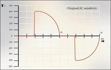
Typically light dimmers are manufactured using a Triac as the power control device. These electronic parts are semiconductors not dissimilar to transistors. An electronic circuit determines the point in time at which they turn ON (conduct). The ON state continues until the next zero-crossing point, at which point the device turns itself OFF. The electronic circuit then provides a delay, which equates to the dimness of the lamp, before turning the control device back on. The slight capacitance of the load, filters the chopped waveform resulting in a smooth light output.
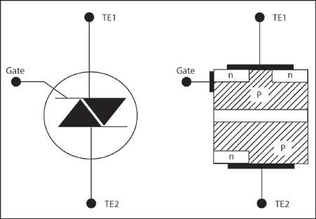
The Triac has two main terminals. TE1/ TE2 (power in and load out) and a single gate connection. The main terminals are connected to both p and n regions since the current can be conducted in either direction. The gate is similarly connected, since a Triac can be triggered by both negative and positive pulses.
Some controllers use a microprocessor control with the above timing function being handled by an analogue circuit. More sophisticated systems, called digital dimmers, operate the switching direct from microprocessor. This has the advantage of greater reliability, quieter operation, lower cost and smaller controls.
For more technical information about dimmers visit www.sprags.com – Anything you want to know about dimmers


